
Insights
Teaching a neural network to fly — without redesigning it for flight

A PROJECT BY EVOLEO, AIRBUS DEFENCE AND SPACE & TUM
AI4NCA — ESA-backed technology development
Inside AI4NCA: how a maritime-safety AI model went from a laptop GPU onto a flight-representative processor board built to European space-industry standards — and what happened when it got there.
- TRL 4→6
- Board maturity raised over the project, verified as flight-representative hardware
- 0.60
- Mean detection accuracy (mAP) across the full test set
- 5.3 FPS
- Images processed per second, running on the board itself
- ~543 days
- Estimated time in orbit before radiation effects would start to matter
THE PROBLEM
Most on-board AI accelerators are designed once, for one job
AI4NCA — “AI for Non-Mission Critical On-Board Data Processing” — set out to answer a narrower, more practical question: can a generic, programmable hardware accelerator run modern deep-learning models on a spacecraft, within the size, power, and radiation constraints of a non-mission-critical processing unit, without being redesigned for each new network?
A chip built for one specific network is more efficient at that one job. A generic, programmable accelerator trades away some of that efficiency for the freedom to run a variety of neural networks over its lifetime — useful when a mission's needs might change after launch. AI4NCA tests that trade-off directly, carrying two independent AI use cases through the same pipeline: shrink a conventional neural network down to run on limited hardware, load it onto real silicon, and measure what survives the trip.
TWO USE CASES, ONE PIPELINE
One model went to hardware. The other stayed in simulation — deliberately.
DEPLOYED · ON-BOARD
Maritime Safety
Autonomous detection, classification, and length estimation of ships — fishing and non-fishing — from satellite radar imagery, using a modified YOLO detector shrunk down to run on limited hardware.
- 8,621 satellite images
- Training data
- Modified YOLO
- Network
- The flight-representative board
- Runs on
- Full on-hardware test campaign
- Verified by
SIMULATION ONLY
Active MTF Control
Active-optics wavefront-error correction for larger-aperture optical instruments, using a modified EfficientNetB0 to work out the correction needed from a pair of photos.
- 1.5 m, single circular
- Aperture
- Modified EfficientNetB0
- Network
- Simulation only — no hardware
- Runs on
- 24.03 nm mean residual error
- Result
THE HARDWARE
A board that had to prove it was the real thing, not a stand-in
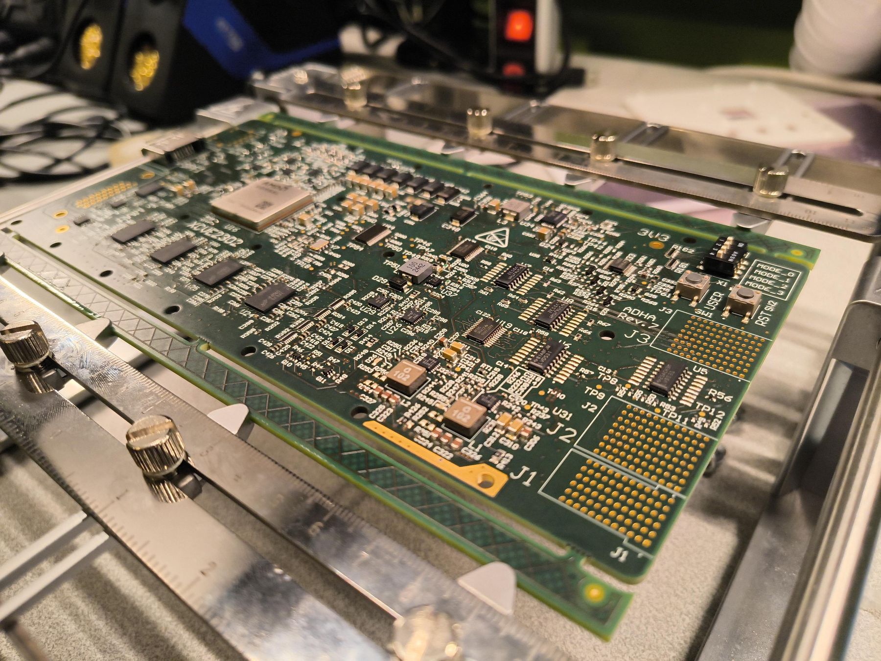
The processor at the centre of AI4NCA is an AMD-Xilinx Versal AI Edge chip — and the deliverable wasn’t just running code on it. The board carrying that chip had to be verified as form, fit, and function equivalent to a real flight module: the same size, the same connectors, the same behaviour a spacecraft would actually see.
THE CHIP
Versal AI Edge
Pin-compatible with a radiation-tolerant flight version of the same part. It combines a dedicated AI compute array with a block of reconfigurable logic — the “programmable accelerator” that lets it run more than one kind of neural network.
ADHA STANDARD
Built to slot into a real spacecraft bus
The board was reviewed against ADHA, a European space-industry architecture standard covering module dimensions, the backplane connector it plugs into, and how it talks to the rest of a spacecraft — not a lab-only prototype, but a module built to the same rulebook a flight unit would answer to.
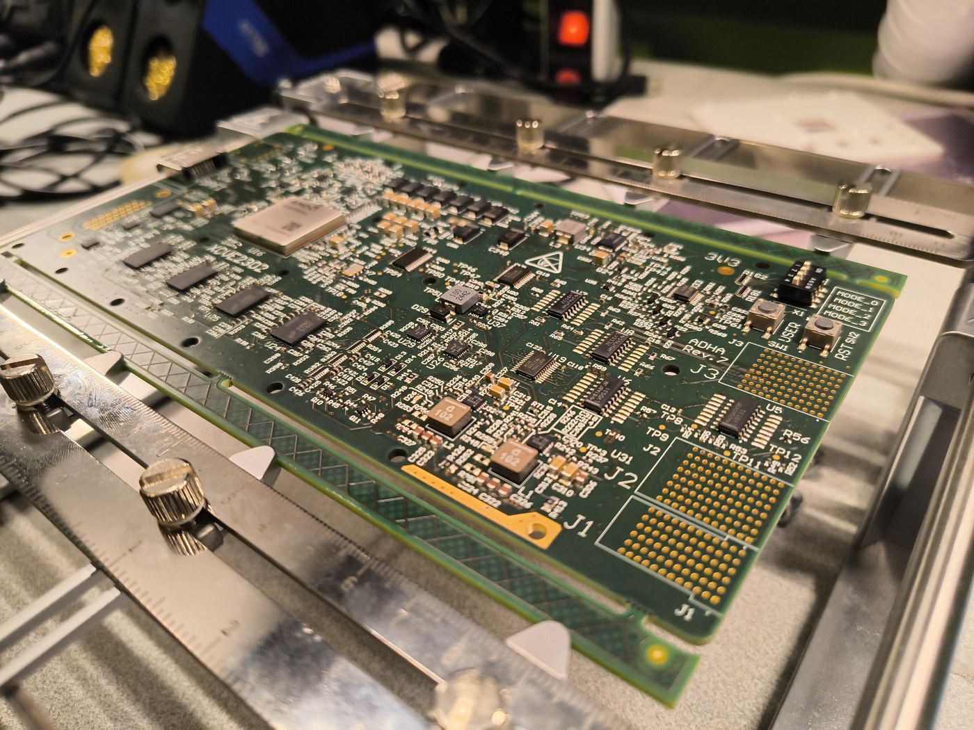
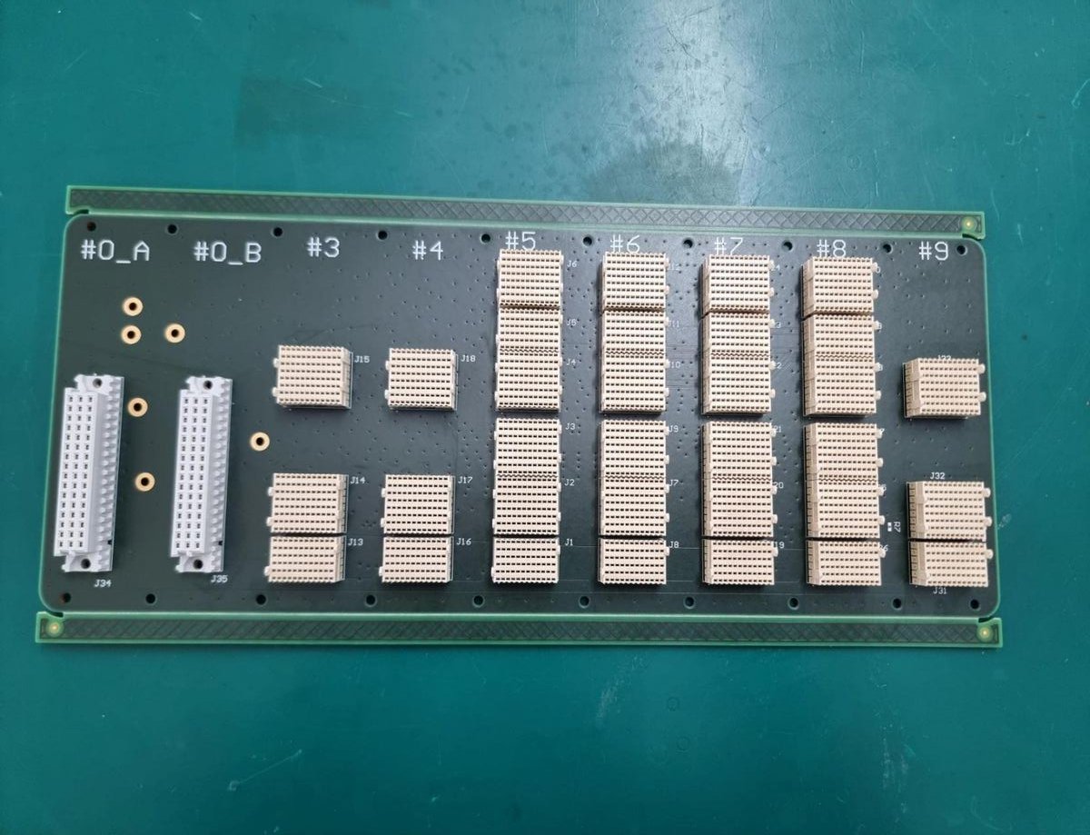
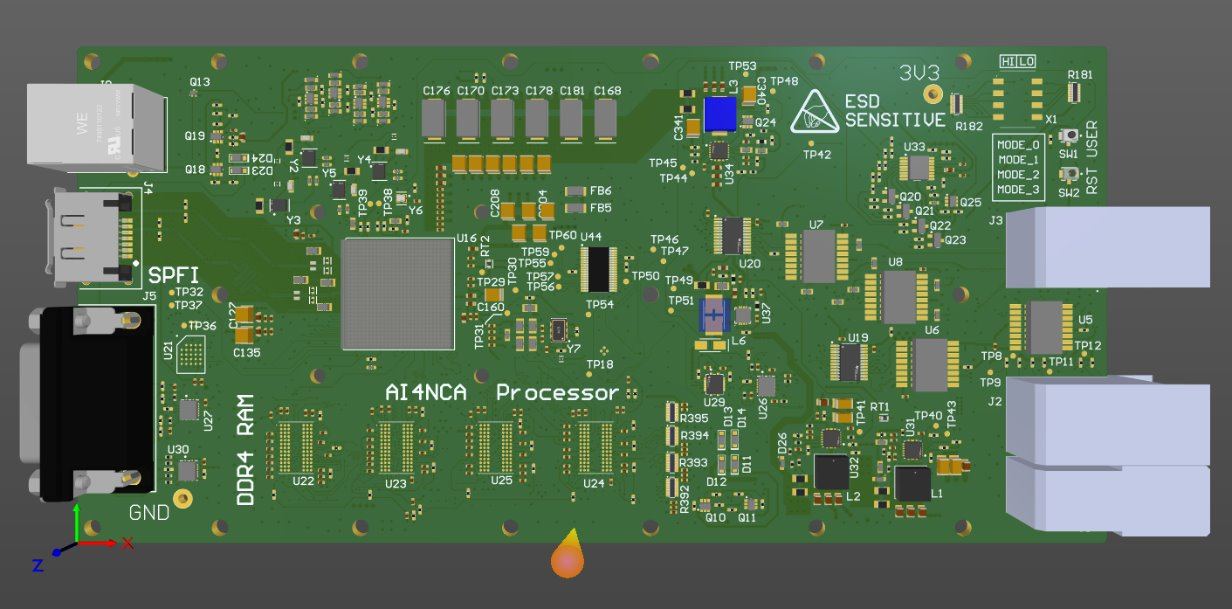
Testing didn’t happen only on EVOLEO’s own board. Part of the campaign ran on ESA’s OBPAI facility — a remote evaluation platform that gives approved projects controlled access to the same family of flight-representative chip, similar in spirit to how a cloud development environment gives you access to a remote machine without that machine sitting on your desk. It's a way of testing against representative hardware without every team needing its own physical board.
THE TOOLCHAIN
From a floating-point model to something the chip can run
Both networks were trained conventionally — ordinary floating-point arithmetic, on a regular GPU. Getting from there to the board runs through AMD’s Vitis AI toolchain: it compresses the model’s numbers down from floating-point to 8-bit integers, then compiles the result into a form the chip’s reconfigurable logic can execute directly.
That compression step is where a lot of the real engineering happens. Going from floating-point precision to 8-bit integers isn’t free — it’s a controlled loss of precision, and part of AI4NCA’s job was to measure exactly how much accuracy it cost.
| Task | Metric | Before compression | After compression |
|---|---|---|---|
| Detection | Accuracy | 0.659 | 0.638 |
| Classification (fishing) | Accuracy | 0.604 | 0.567 |
| Length estimate | Accuracy | 0.713 | 0.709 |
Measured on a held-out set of 862 images. The accuracy lost to compression stayed under 5% on every task — the margin that makes running the model on board worthwhile in the first place, instead of sending raw imagery back to the ground for processing.
VALIDATING THE MODEL
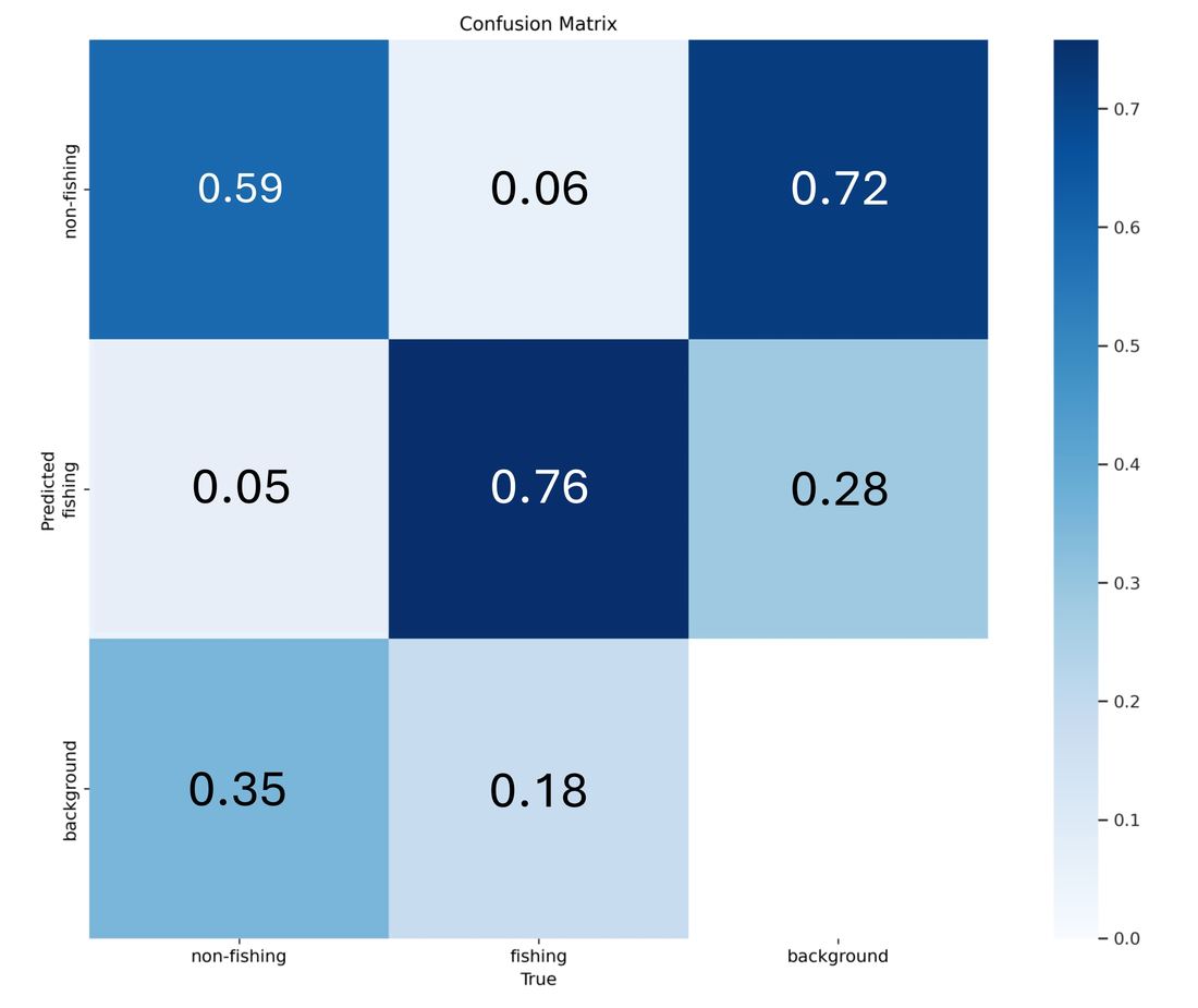
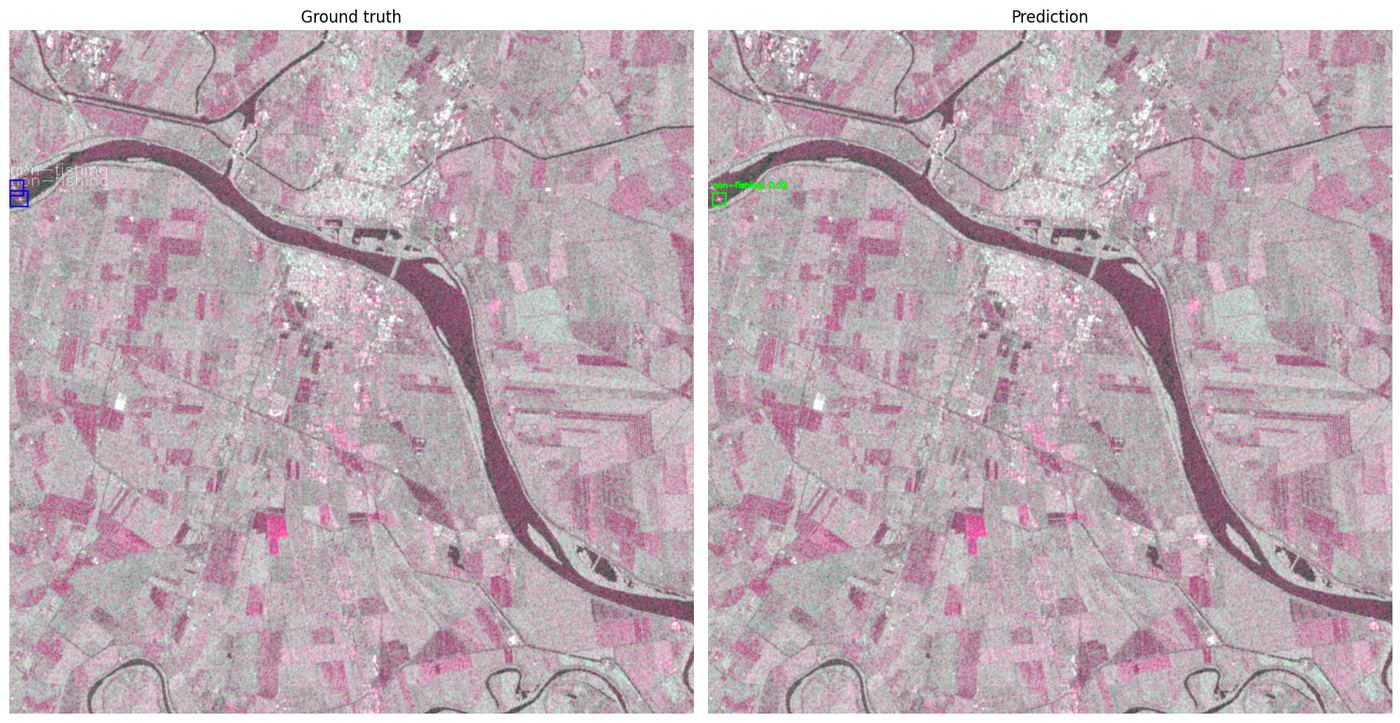
Before it ever touched flight hardware
These two results come from an earlier stage of the project — the trained model evaluated on a development computer, against a large test set, before compression and before it was ever loaded onto a board. They show the model works; the hardware results further down show it keeps working once it’s deployed.
RUNNING ON THE BOARD
What actually happened once the model was on real hardware
From here on, every number was measured with the compressed model actually running on the processor board — not simulated, not estimated from the development-computer results above.
- 0.778
- Detection accuracy score, on board
- 109.1 MB
- Memory the model takes up once loaded
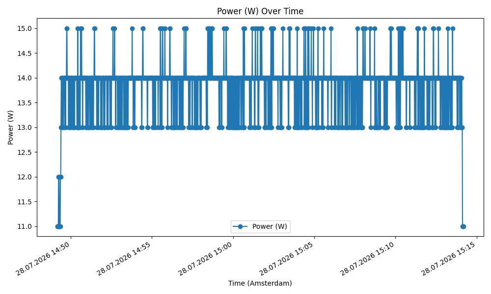
- 11–15 W
- Power draw, idle through to active inference
- 5.3–6.7 FPS
- Images processed per second, on board
A combined measure of how rarely the model misses a real ship and how rarely it flags something that isn’t one. 1.0 would be perfect on both counts.
Small enough to share the board’s memory comfortably with everything else the processor needs to do.
Roughly what a bright household lightbulb uses — modest by design, since spacecraft power budgets leave little room to spare.
5.3 FPS reflects a single image end-to-end; 6.7 FPS is the steady-state rate across 1,000 back-to-back runs. Either way, a new image is fully processed roughly every fifth of a second — without waiting on a link to the ground.
RADIATION ROBUSTNESS
Simulating nearly a year and a half in orbit, one bit-flip at a time
Cosmic radiation in orbit occasionally flips individual bits in a chip’s memory — including the numbers that make up a trained model. Left unprotected, enough of these “single-event upsets” will eventually corrupt a model's accuracy. To find out how many is “enough,” the team deliberately corrupted increasing numbers of bits in the deployed model and re-measured its accuracy after each step, then compared that against how often such upsets are actually expected to happen in orbit.
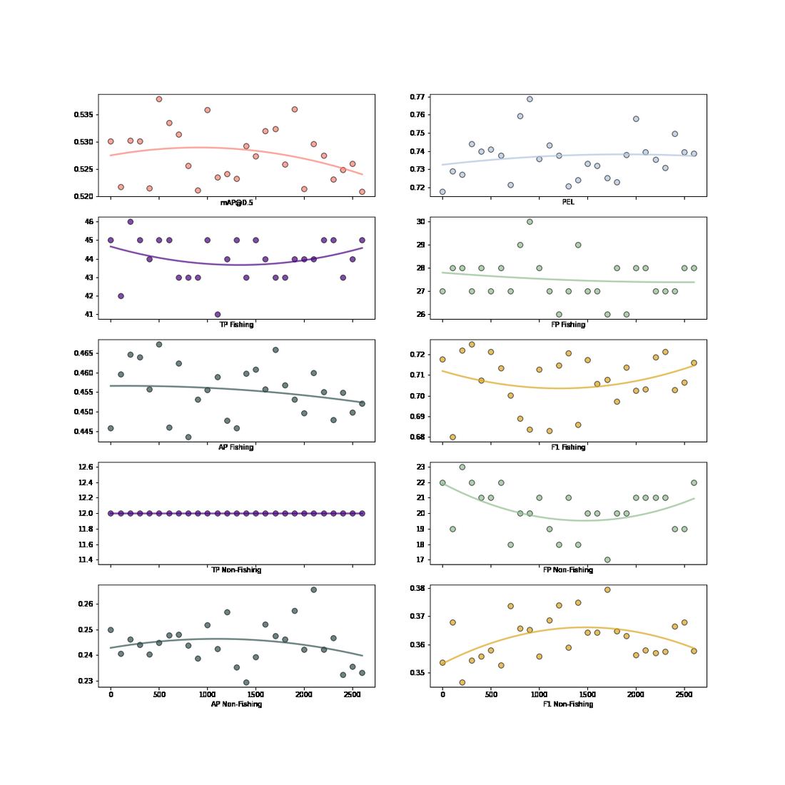
A trained neural network has a lot of built-in redundancy — the same over-parameterization that makes it easier to train also means it can absorb a certain number of corrupted values before its output visibly suffers. At the rate radiation upsets are expected to actually occur in orbit, that redundancy was enough to cover roughly 543 days — about a year and a half — before any measurable accuracy loss, with no additional radiation-hardening built into the software.
SECOND USE CASE — SIMULATED ONLY
Reading a wavefront error out of two ordinary-looking photographs
Active MTF Control takes a different kind of input: two images of the same scene, one in focus and one deliberately thrown out of focus. The gap between them encodes exactly how an optical system’s lens or mirror is distorting the image — and a modified EfficientNetB0 was trained to read that gap back out as a correction.
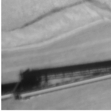
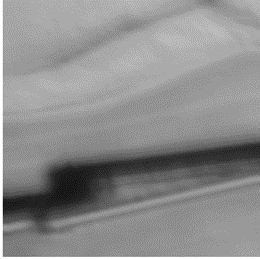
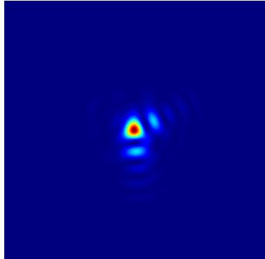
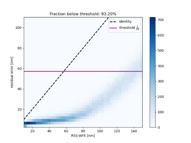
On average, the correction left an error small enough to be close to the theoretical limit of what the optics themselves could resolve — comparable to the softening you’d get from ordinary sensor noise. No physical optical bench existed to test this against, so the whole correction loop — camera, distortion, and fix — was reconstructed and run entirely in simulation. It was never deployed on real hardware, and the project treats it accordingly: a validated idea, not a flown one.
WHERE THIS GOES NEXT
From a validated workflow to a qualified, flyable one
Both use cases now have a working answer to “can this run on non-mission-critical hardware?” — one proven on real silicon, one proven in simulation. The next steps are to carry the maritime-safety workflow through formal flight qualification, and to work toward demonstrating it in orbit.